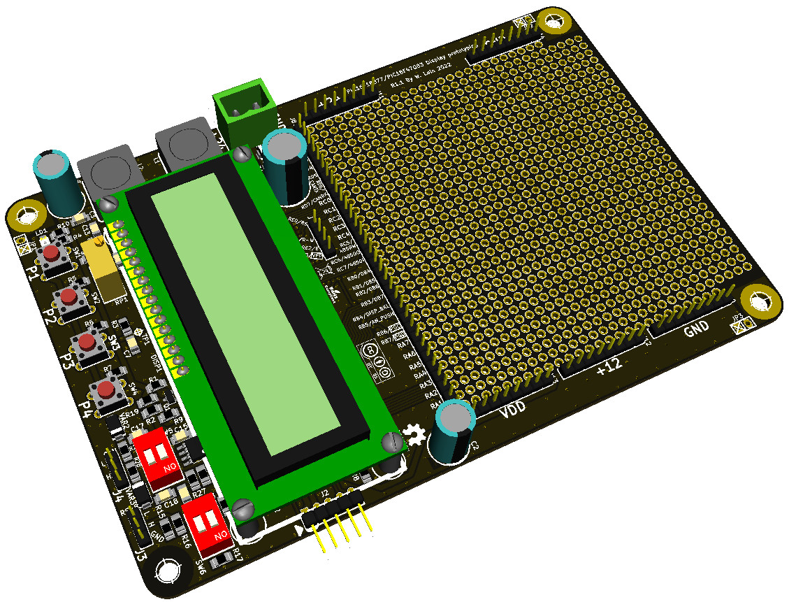
Display proto board

Prototyping board for PIC16F and PIC18F


Last update: 18/03/2022


All the material present in this page is covered by the Creative Commons Attribution-Non commercial-ShareAlike license.
Creative Commons License

PROJECT
Prototyping board for PIC16F and PIC18F

AUTHORS
Walter Lain

SPECIFICATIONS
This project started as a simple fork of a small display+push board that I made for work purposes. Then, as I mulled over it for about a year, I decided to improve it. The initial board had a simple LDO design and only a single I/O, no communications and nothing else. It used a "small" PIC16F15344, with most IOs used up by the 8-bit display data bus. It was, simply put, a board designed specifically for a single use.
I started thinking about using a bigger MCU like the PIC16F15376, leaving all the rest the same, but then I realized that some other recent families of PIC16 and PIC18 share the exact same pinout and remappable pins structure. So I delved deeper into it, and chose to make it a prototyping board for as many different MCUs as possible. I wanted a communication line (RS-485) and less pins used up by the display, so I changed the 8-bit bus to a 4-bit bus, and I added an optional small piece of circuitry to provide dimming and/or on/off control for the backlight. I also decided, since it was meant to prototype, to swap the LDO with a more powerful switching supply. I ended up putting 2, a 12V-2A and a 5V-2A. Given that one of the compatible MCU families has a CAN module, I also added a CAN circuit. Finally, I took out every single I/O pin and made it available on a pin header, close to a 32x30 2.54mm solderable thru-hole pad grid for prototyping. Along that grid are also available headers for 24V (unregulated), 12V and 5V supplies.

The final specifications are as follows:
  • Size: 100x150mm, 2-sided FR4 board with standard thickness
  • Power supply: 24Vdc 2A
  • On-board supplies: 12V 2A, 5V 2A
  • Communications: 1x RS-485, 1x CAN, both with selectable termination
  • Display: LCD 2x16, standard HD44780 4-bit interface, controllable backlight
  • Buttons: 4 NO, available as a single analogic input
  • I/O: up to 36 available, of which up to 35 usable as analog
  • MCU compatibility: PIC16F15375/76, PIC16F18875/76/77, PIC18F45/46/47 K42, PIC18F45/46/47 Q43, PIC18F46/47 Q83
  • Programming/debugging: PicKit/ICD interface on a 5-way 90° angled connector

     
    PIC16F15375
    PIC16F15376
    PIC16F18875
    PIC16F18876
    PIC16F18877
    PIC18F45K42
    PIC18F46K42
    PIC18F47K42
    PIC18F45Q43
    PIC18F46Q43
    PIC18F47Q43
    PIC18F46Q83
    PIC18F47Q83
    Speed
    8MIPS
    8MIPS
    8MIPS
    8MIPS
    8MIPS
    16MIPS
    16MIPS
    16MIPS
    16MIPS
    16MIPS
    16MIPS
    16MIPS
    16MIPS
    FLASH
    14kb/8kw
    28kb/16kw
    14kb/8kw
    28kb/16kw
    56kb/32kw
    32kb/16kw
    64kb/32kw
    128kb/64kw
    32kb/16kw
    64kb/32kw
    128kb/64kw
    64kb/32kw
    128kb/64kw
    RAM
    1kb
    2kb
    1kb
    2kb
    4kb
    2kb
    4kb
    8kb
    2kb
    4kb
    8kb
    4kb
    12.5kb
    EEPROM
    0
    0
    256b
    256b
    256b
    256b
    1kb
    1kb
    1kb
    1kb
    1kb
    1kb
    1kb
    Storage Area Flash
    224b
    224b
    0
    0
    0
    0
    0
    0
    0
    0
    0
    0
    0
    I/O pins
    36
    36
    36
    36
    36
    36
    36
    36
    36
    36
    36
    36
    36
    8bit timers with HLT
    1
    1
    3
    3
    3
    3
    3
    3
    3
    3
    3
    3
    3
    16bit timers
    2
    2
    4
    4
    4
    4
    4
    4
    4
    4
    4
    3
    3
    16bit CCP (10bit PWM)
    2
    2
    5
    5
    5
    4
    4
    4
    3
    3
    3
    3
    3
    10bit PWM
    4
    4
    2
    2
    2
    4
    4
    4
    0
    0
    0
    0
    0
    16bit dual PWM
    0
    0
    0
    0
    0
    0
    0
    0
    3
    3
    3
    4
    4
    Complementary Waveform Gen
    1
    1
    3
    3
    3
    3
    3
    3
    3
    3
    3
    3
    3
    Signal Measurement Timer
    N
    N
    Y
    Y
    Y
    Y
    Y
    Y
    Y
    Y
    Y
    Y
    Y
    Numeric Controlled Oscillator
    1
    1
    1
    1
    1
    1
    1
    1
    3
    3
    3
    3
    3
    Configurable Logic Cells
    4
    4
    4
    4
    4
    4
    4
    4
    8
    8
    8
    8
    8
    10bit ADC (ch)
    35
    35
    35
    35
    35
    0
    0
    0
    0
    0
    0
    0
    0
    12bit ADC (ch)
    0
    0
    0
    0
    0
    35
    35
    35
    35
    35
    35
    35
    35
    5bit DAC
    1
    1
    1
    1
    1
    1
    1
    1
    0
    0
    0
    0
    0
    8bit DAC
    0
    0
    0
    0
    0
    0
    0
    0
    36
    1
    1
    1
    1
    Comparators
    2
    2
    2
    2
    2
    2
    2
    2
    2
    2
    2
    2
    2
    Zero Cross Detect
    Y
    Y
    Y
    Y
    Y
    Y
    Y
    Y
    Y
    Y
    Y
    Y
    Y
    High/Low voltage detector
    N
    N
    N
    N
    N
    Y
    Y
    Y
    Y
    Y
    Y
    Y
    Y
    Data Signal Modulator
    0
    0
    1
    1
    1
    1
    1
    1
    1
    1
    1
    1
    1
    UART
    2
    2
    1
    1
    1
    2
    2
    2
    4
    4
    4
    3
    3
    UART+Protocol Support
    0
    0
    0
    0
    0
    0
    0
    0
    1
    1
    1
    2
    2
    CAN
    0
    0
    0
    0
    0
    0
    0
    0
    0
    0
    0
    1
    1
    SPI
    2
    2
    2
    2
    2
    1
    1
    1
    2
    2
    2
    2
    2
    I2C
    2
    2
    2
    1
    1
    1
    1
    1
    DMA
    0
    0
    0
    0
    0
    2
    2
    2
    6
    6
    6
    8
    8
    Windowed Watchdog
    Y
    Y
    Y
    Y
    Y
    Y
    Y
    Y
    Y
    Y
    Y
    Y
    Y
    16bit CRC
    N
    N
    Y
    Y
    Y
    Y
    Y
    Y
    Y
    Y
    Y
    N
    N
    32bit CRC
    N
    N
    N
    N
    N
    N
    N
    N
    N
    N
    N
    Y
    Y
    Vectored Interrupts
    N
    N
    N
    N
    N
    Y
    Y
    Y
    Y
    Y
    Y
    Y
    Y
    Temperature Indicator
    Y
    Y
    Y
    Y
    Y
    Y
    Y
    Y
    Y
    Y
    Y
    Y
    Y
    JTAG Boundary Scan
    N
    N
    N
    N
    N
    N
    N
    N
    N
    N
    N
    Y
    Y
    Reference


    The board can be easily ordered from small batch PCB manufacturers (such as JLC, Itead or Seed).
    The components are all in SMD technology except for the MCU itself and a very few other parts. This was done to allow easy swap of the MCU whenever needed for a different project. With a bit of dexterity and a decent soldering iron the board can be assembled by hand in a couple of hours.

    DOCUMENTS
    All the files needed for production are already packed in this zip file, so if you wish you can simply download it and put it on production.
    This is the full BOM with the order codes for Mouser, with the right quantities to make 1 board.

    Kicad project (you will need some libraries from here)
    Basic software demo (Display and push)

    PDF documents
    Schematic
    PCB (all layers)
    Flow charts for all the software routines
    PIN mapping for compatible MCUs

    The board can be used in any way while inside the boundaries of the CC-BY-NC-SA license. However, I'd advise you to give it a careful check if you plan to use it for anything else than an hobbyist testboard.The circuit was tested in all ways possible, but I cannot guarantee that it will always work in all conditions.

    Please don't ask me if I can sell kits or parts or anything else. The answer is NO, because it would not be convenient for you. If you can't assemble the board by yourself, some of the small batch providers that I linked before can also assemble the boards for you, or you can ask an electronics lab close to your place.


    Impaginazione by KCS'81